
UVCto3D is a Linux GUI program for scanning 3D objects in colour using a Logitech 9000 Pro camera, a line generating laser and a turn-table. Over two passes it will first capture the shape of an object based on laser position seen from the camera and then secondly, without the laser it will revisit those pixels in natural light to find the natural colour. Resolution is decided by turn-table rotation speed and the camera. At 5 fps and with most of the 1200 pixel height utilised, a height to width balanced scan would rotate the table in exactly 4 minutes. The result is saved out using .obj+.mat+.png files, which can be imported to MeshLab, Blender and many others.
The GUI is organised so that you set up the parameters once, and then scan as many times as required. Only moving the camera/laser/turntable positions will disturb the parameters. It is possible to use two copies of UVCto3D at the same time, each reading from a different camera. You could then capture more detail, such as when the camera can't see the laser because part of the object is in the way.
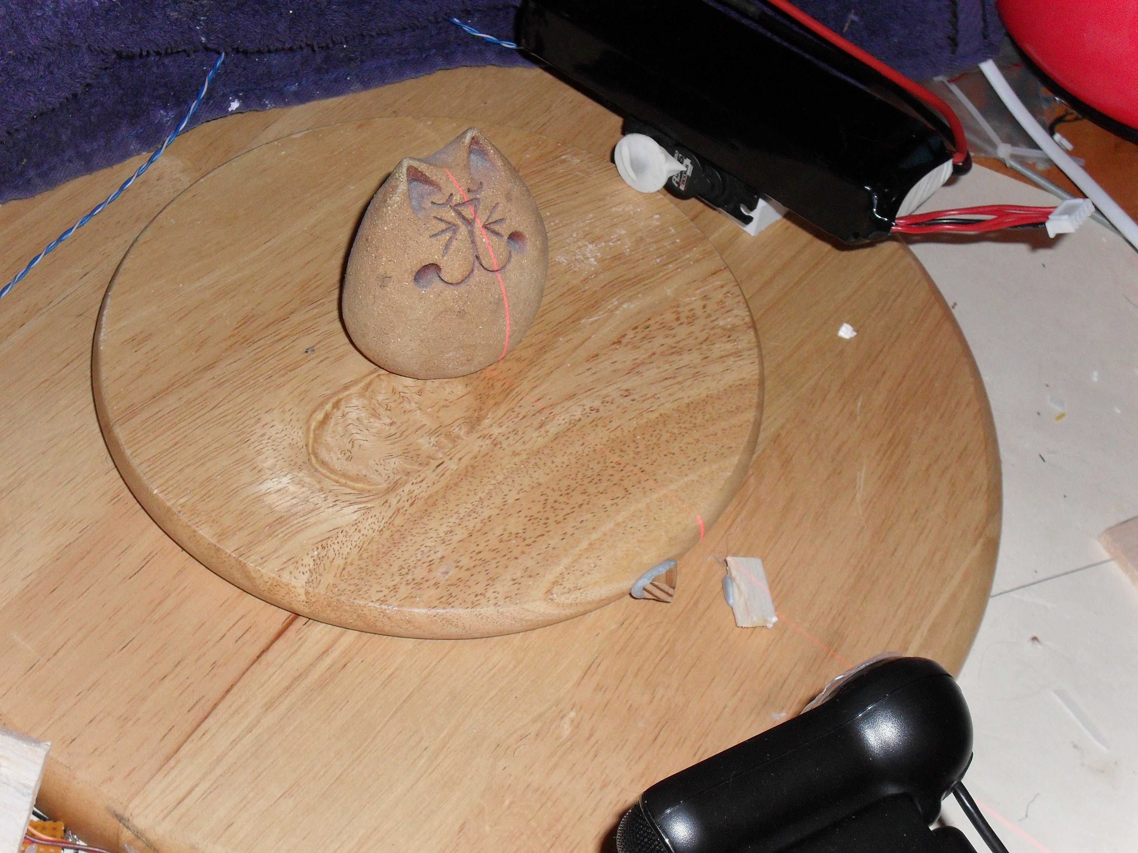
Example scan, a ceramic cat, cleaned up with a few clicks in MeshLab:
Which came from: As scanned, crop noise, normalise texture colour and finally, Laplace smoothing.
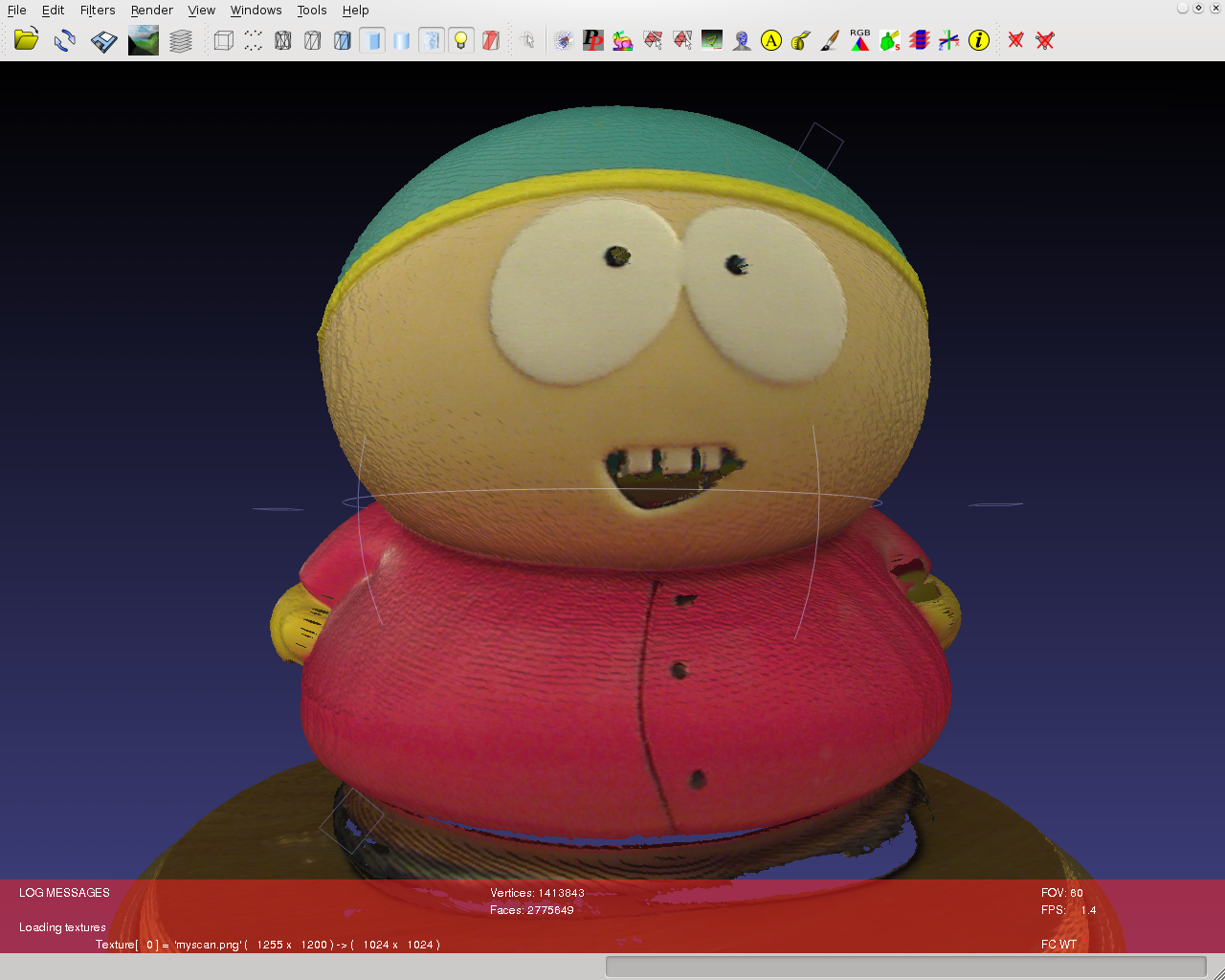
Example scan of a cartoon chartacter, originally a money box.
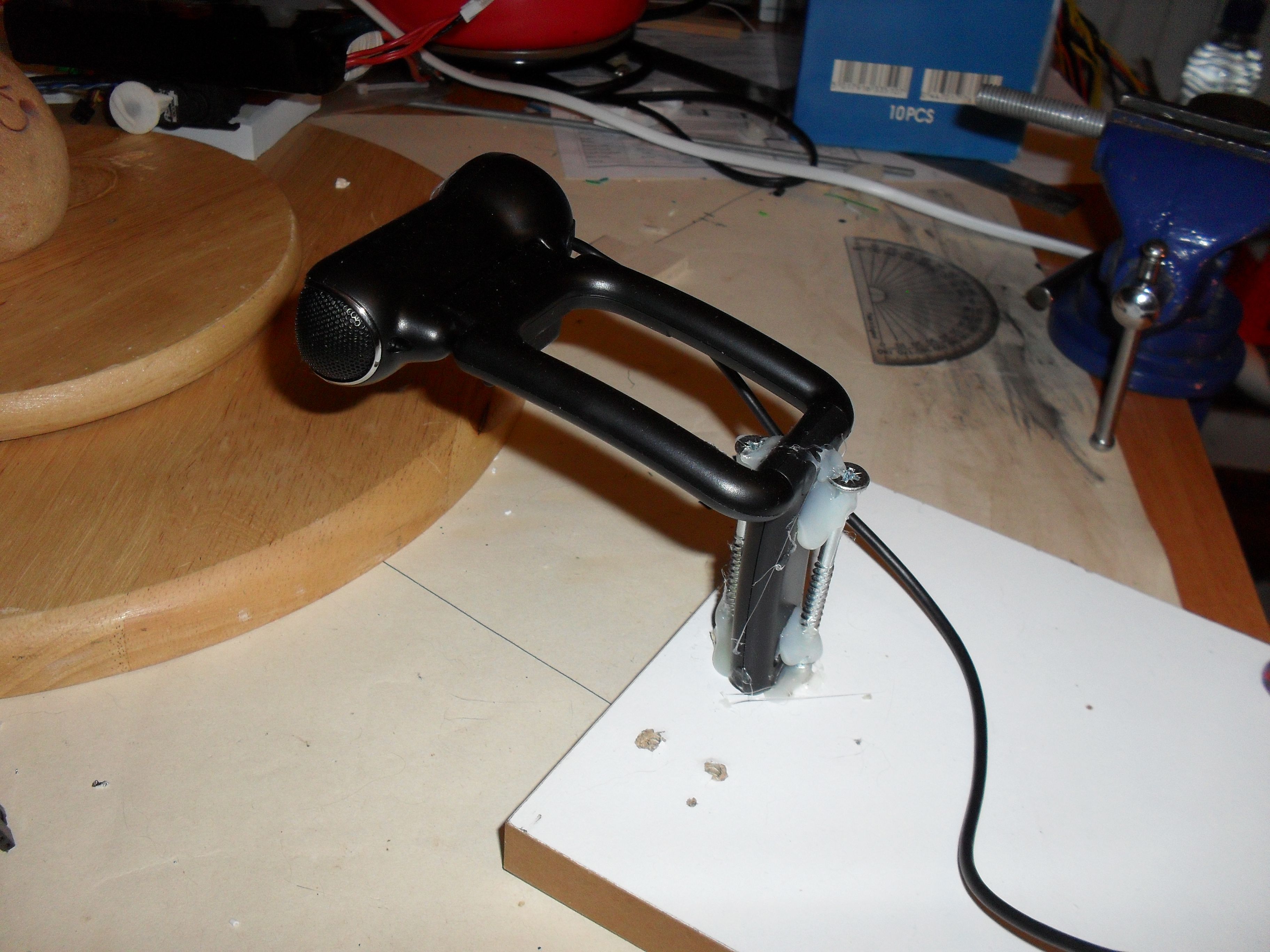
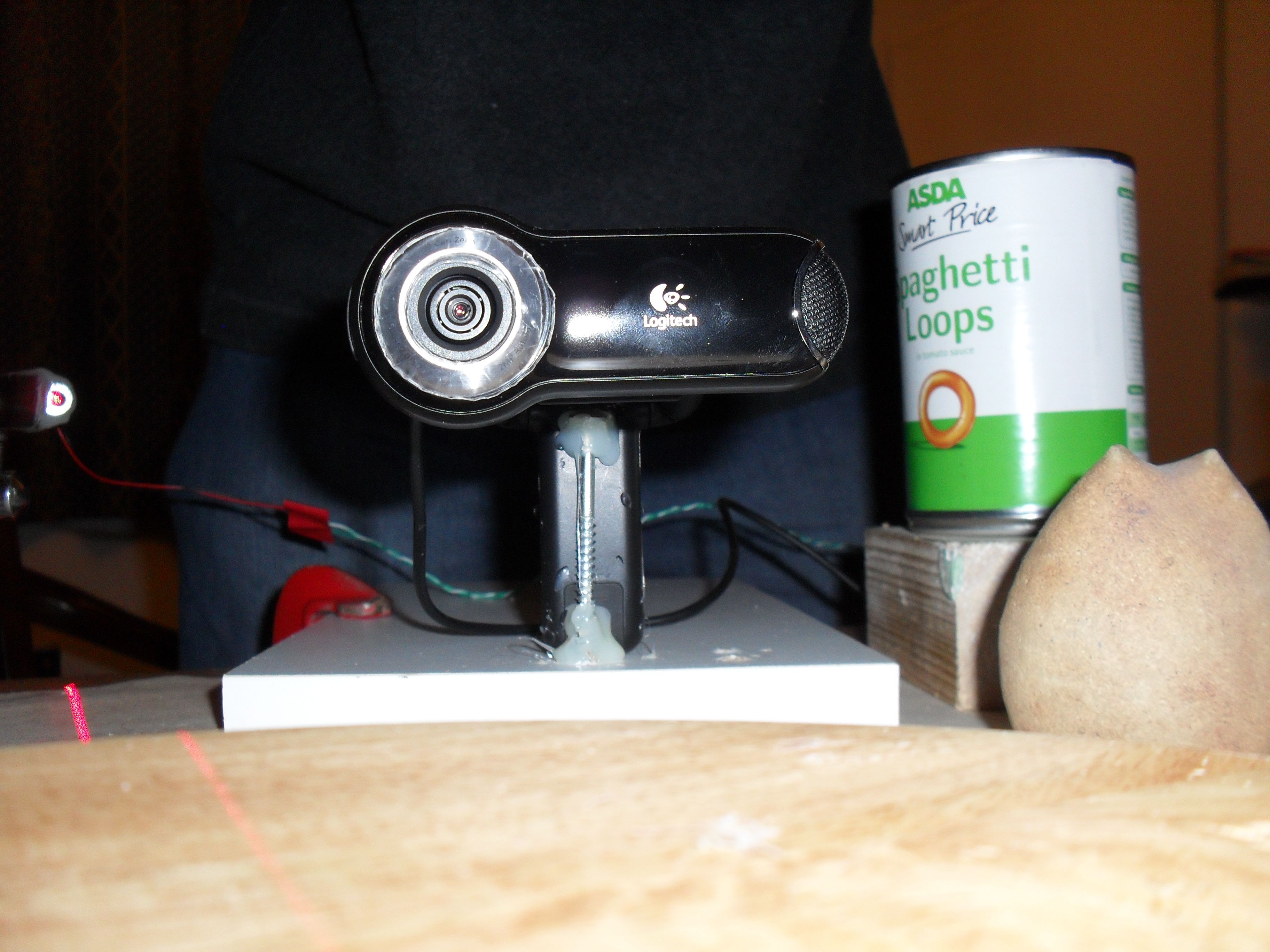
Logitech Pro 9000 camera, also now sold as Quickcam Pro. Possibly any UVC capable web cam. Importantly, it is capable of 1600x1200 and produces uncompressed YUYV raw image (ie. 1600x1200 luminosity, 800x1200 colour), free from jpeg artifacts. To mount it, I screwed two 3" screws into a peice of flat wood, with just enough room between them for the "mount" of the camera to jam between. Hot glue was then applied between the mount and the screws, resulting in the camera being reliably (as long as it isn't touched) attached to a peice of wood, which is G-clamped to the desk.
UVCto3D should compile on any Linux, I used Debian Squeeze. The GUI does not use a standard GUI library (that looked to be far too much effort), so has minimal X11 dependencies and no convoluted build process.
uvcdynctrl is part of libuvc and required for enabling manual focus, with something like:
uvcdynctrl --import=/usr/share/uvcdynctrl/data/046d/logitech.xml
Auto focus changes perspective, so is essential to get this working.
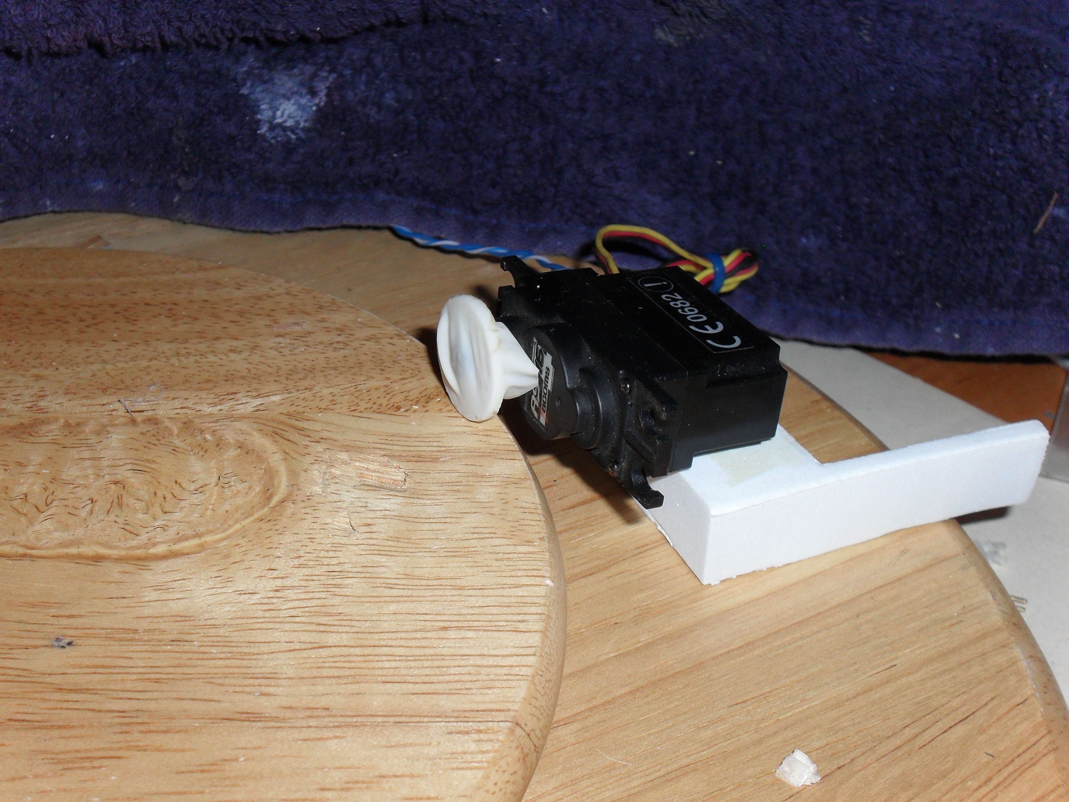
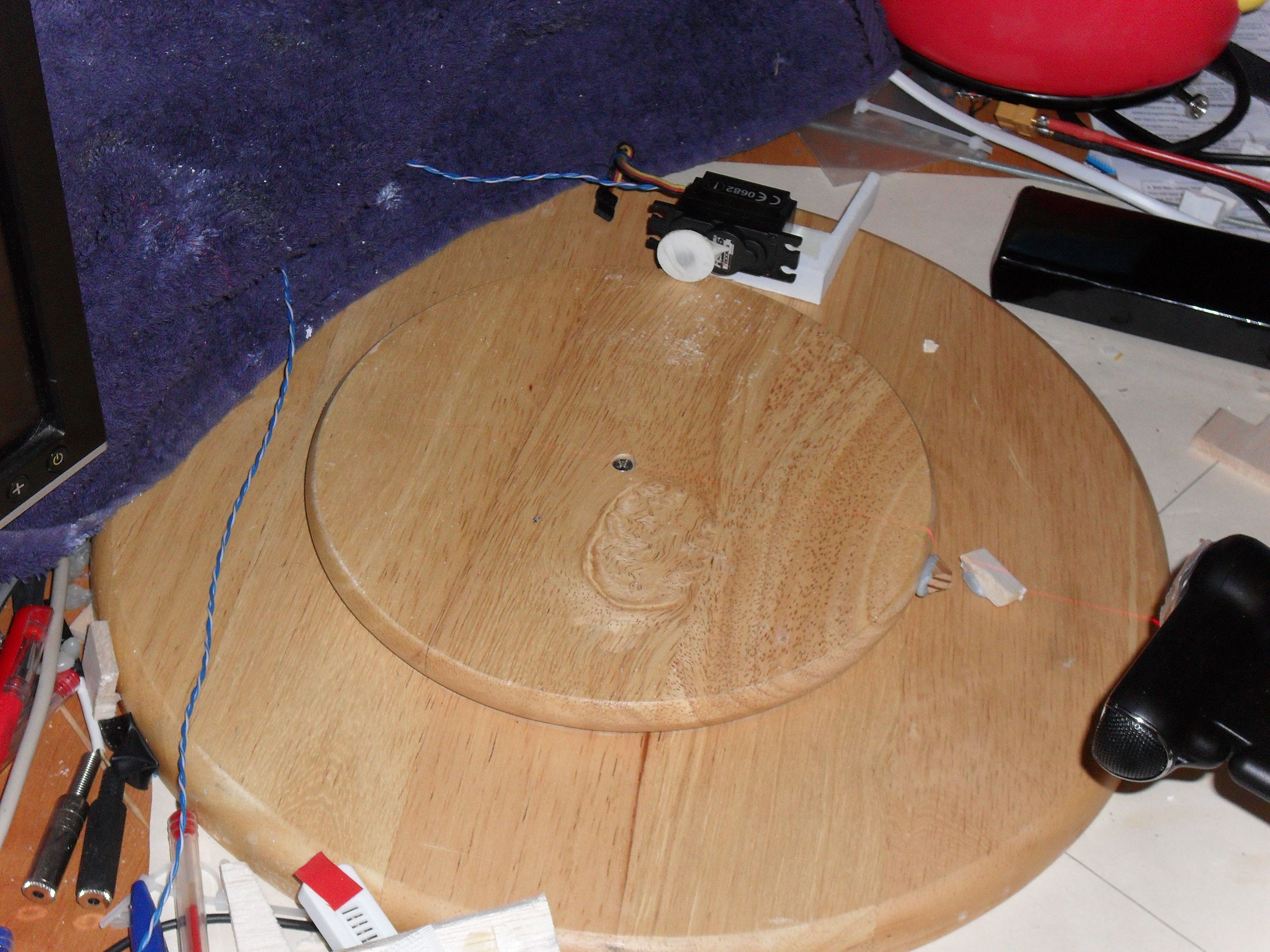
The turn table should be of a size for scanning the objects you have in mind, without leaning or wobbling under the weight, and rotate slowly and steadily. One rotation per minute is probably as quick as you would want, approximately a scan per degree. The resulting scan is recognisable but noisy. It is better to scan more slowly, and use MeshLab (Filter->Colour->Laplace Smooth) to average out some of the noise. I used a Lazy Susan turn-table, and modifed an RC servo - cut out the end stops, cut out the internal circuit board and made a circuit to continuously pulse the servo motor. The edge of a 0.75" servo horn was coated in puncture repair glue and the tip of a latex glove stretched over. The servo horn leans on the Lazy Susan, with the servo weighted down (the weight isn't shown on the photo) - all of which allows the Lazy Susan to wobble slightly and me to quickly remove the servo and manually rotate the Lazy Susan close to a start point without waiting.
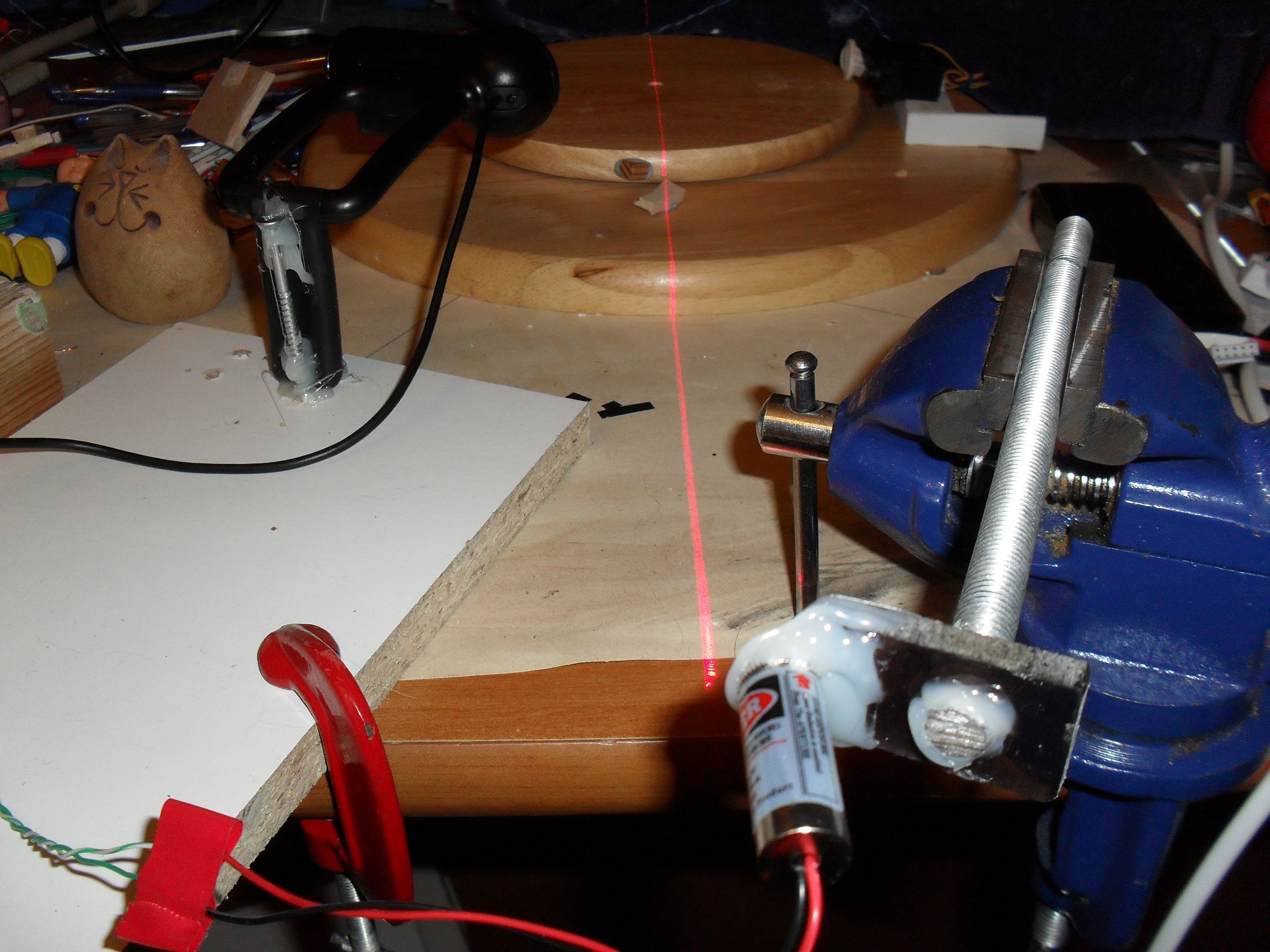
The laser I used was bought from the usual on-line seller of misc stuff. A fiver for a 5mW red dot laser that came with a lens that produced a band instead of a dot. Looking closely, the band is actually many dots, but that is beyond the resolution of the camera when used like this. 5mW is fine for light objects, but the red light does tend to be absorbed by black objects. It needs more power, or maybe moving the laser closer to the object, as the 90 degree beam spread looses a lot of that 5mW. I mounted my laser to a round metal bar with hot glue, the bar was then held in an adjustable vice. You might find is easier to only make the vertical of the laser adjustable, and move the turn-table to have the laser light crossing the centre of rotation.
MeshLab is a great package for removing artifacts and noise from the raw scan. A raw scan will contain a lot of noise, generated from pixels in the background. They are hard to reliably filter out, but as a human you will easily recognise them. Using MeshLab with Filter->Cleaning and repairing->Removed faces longer than.. to remove the wildly long edges, and then deleting the halo of "short" noise by rotating the object to be looking from above, selecting Edit->Select faces in a rectangular region, picking the object you want, then selecting Filter->Selection->Invert selection to select the circular halo of noise, then Filters->Selection->Delete selected faces and vertices. Save it out and you have a fairly clean scan. I'm sure there are other filters that can improve on the scan some more. It might also be worth loading the texture in the GIMP and improving the white-balance, as the scan colour can be a little flat.
Not on the list but an essential item - controlled lighting. For the laser scan you will want the object to be in darkness, illuminated only be the laser. Total darkness is not required, but UVCto3D must be able to pick out the brightest pixels as those directly hit by the laser, anything else will appear as noise. For the second phase of the scan, to capture colour you will want a bright natural light. Clouds going by or energy saving bulbs that are still warming up will show up on the scan as changes in brightness, a gradient. Especially noticeable when the colour texture is wrapped around the object and the first and last colour scans are side by side.
Turn table: When viewed from above, UVCto3D assumes it rotates anti-clockwise. As mentioned above, I use an RC servo and friction drive. Useful to reposition the turn-table without waiting it to rotate, but friction drives can be unreliable. Somewhere between the friction drive and the servo driver circuit, in my set-up the rotation rate is not stable. Consequently I would recommend making sure rotation rates are repeatable, ideally with a stepper motor and toothed drive. The ability to vary the speed, between say slow and fast, or reverse the direction, would also be useful for resetting during the colour scan, and if you couldn't remove the drive from the turn-table, it would be essential. Later on you will also need to measure distances from the center of rotation, both towards the laser and vertically. A set square and ruler is required for this. It is also essential to put some sort of mark on the turntable so that you know it has done a full rotation and so that you know where to start from for the colour scan phase. I have a mark on the rotating part of the turn-table and a mark on the base, so what when the two meet, that is the start/end of a scanning phase. It is also useful to see the mark in low light during the depth scan phase, so put it at the point illuminated by the laser.
Camera: To get the most resolution from the camera it should be as close as possible to the object to be scanned. However, you must also take other things into account i) focal depth and ii) overly specific camera position. Focal depth becomes a problem because the camera is operating with fixed focus yet is looking at an object that changes in depth. As the laser image looses focus, the 3D location will become more noisy. So there is a trade off. Also, it takes time to calibrate the scanning set-up, so you need to consider how useful it will be to have the camera at a particular depth. Ideally the camera should be perpendicular to the turn-table, though a small amount of looking up/down is ok. I'm fairly sure this is accounted for in the calibration parameters. The camera can also have a small amount of lean (rotation of the cameras vertical compared to the rotation relative to vertical on the turn-table). It is hard to get this exact by physically moving the camera, so again, there is a calibration parameter that takes it into account. On the turntable, looking at camera.
Laser: For the most part the laser is the least demanding item. Give it power and adjust so that the laser light falls across the turn-table, goes through the center of rotation and is in focus at that depth. Rotate the laser so that the vertical beam is vertical to the turn-table. For this I put a set-square on the turn-table. Knowing the set-square will be perpendicular to the turn-table surface, put the set-square edge at the center of rotation, and move the laser so that it hits the set-square at the same distance from the edge, all the way up. My laser is around 40cm from the center of rotation. Works fine on most surfaces, but the red is lost on black surfaces, showing up in the scan as a hole. It is possible putting the laser closer to the object will give it enough power to illuminate black surfaces. On the other hand, it is also possible the extra power will put glare on lighter surfaces, getting in the way of identifying the laser illuminated pixels. Experimentation is required.
Computer: UVCto3D expects to be using the camera at 1600x1200 resolution (though there is no known reason why it couldn't use a lower resolution), and the results of this are displayed unscaled - consequently you will need to display 1600x1200 windows+window decorations. This just about fits on my monitor, but I expect this to be an annoyance to some. Also, I've generally assumed it will be running on a 24bit depth display, stored internally in X11 as 4 bytes per pixel. Any lower colour depths will either i) produce garbled graphics but otherwise work ii) produce a crash. I think it is now fairly unlikely people would run anything other than 24 bit, so it should go unnoticed. For CPU power, my test machine was a 2.3GHz core duo with 5 Gig of ram. UVCto3D and Xorg each put around 30% each load on the CPU (i.e., 30% per core, for both cores). This is presumably all down to continuously updating 1600x1200 images and me not knowing the most efficient way of doing it. The calculations themselves are fairly simple (for a computer), most of the effort is in on-screen feedback. Expect a large scan to use 200-400 megabytes of memory. An overloaded computer can be seen on the terminal. If UVCto3D often says it is skipping an image that came too early, it means there isn't enough time between frame captures to do what needs to be done. Depending on the numbers reported, the warning may or may not be true [this same warning would get in the way of scanning at lower resolutions, the cut-off point would need to be adjustable].
To compile UVCto3D, unpack the contents and type make. If the core parts of the development packages are installed, it should compile without trouble. The UVC part of UVCto3D was taken from the very handy (for this and other projects) uvccapture software. [Must check what it depends on.]
UVCto3D takes 4 parameters, video device (eg. /dev/video0), capture width in pixels, capture height in pixels and
base filename to save the scans as. For example:
./UVCto3D /dev/video0 1600 1200 myscan
You will also need to obtain uvcdynctrl, part of libwebcam. I had to install it from source, but your distribution might have it as a package. As mentioned above, this is required to enable manual focus. Without it, UVCto3D will be unable to change focus, complain a lot about it, and the camera will be stuck in auto-focus, changing focus (and field of view) without warning.
Once running, by default UVCto3D displays the raw camera image and the configuration parameters:

There are two menu buttons on the top of the screen. The left most shows the active mode:-
(CP) configuration mode - Set camera geometry parameters.
(DM) depth scan mode - Start/stop scanning depth.
(CM) colour scan mode - Start/stop scanning colour from the pixels used for depth.
The right button shows the active view, which is useful to determine how well the scan is progressing. They are:-
Raw - Display image directly from camera.
Depth - Show the pixel from each row that UVCto3D found had the brightest pixel.
Colour - Show the colour captured from each pixel, in the position of that pixel.
StripDepth - Show scanned depth as a grey scale, far is at the center of table rotation), near is at the lens of the camera.
StripColour - Show the scanned colour, as a flat image. This will be used as the object texture image.
You would normally only use Depth or StripDepth view during a depth scan, and a Colour or StripColour view during a colour scan, though UVCto3D will not stop you selecting nonsense options.
Calibration of UVCto3D involves putting known objects of known dimensions in view of the camera and clicking on particular points. UVCto3D will save these settings, making them usable for every scan until the camera/laser/turn-table changes position - or you change camera focus.
It is important to set the parameters in order, as some will impact others. The order is not the order they are listed on the menu.
1. The first option to set is camera focus, as this shifts the scale of the whole image. Set it to value that gives a reasonable focus over the whole range depths you expect from the object. Set by clicking on "focus" and moving mouse point left to right. It takes a few frames to focus so give it a chance. The best object for setting the focus isn't necessarily the object you want to scan, something like this might be a better because you can see a lack of focus more clearly.
2. Set the horizon (parameter rawhorizy). This is the height in the image where an object going into the distance moves neither up or down. You can do this in two ways - pile coins on the turn table until the top coin appears completely flat - or put a chequered image in front of the camera, vertical on the turn table but rotated to create some perspective. The cheque that form a horizontal band, that move neither up the image or down the image with distance are at the horizon. As seen in the previous step, the black and white cheque shows the horizon to be approximately at the middle of the height of the image, accurately as possible, here.
3. Turn on the laser and place a set square in view, at the center of rotation. Also, mark on the set square a point high up that can be seen on the camera view. The laser should be rotated so that it hits the center of rotation and is vertical, which means it hits the set square at the same point all the way up. Parameter rawcenter is the center of rotation on the turn table, parameter rawrot is where the laser hits the high point you marked on the set square. Parameter rawhorizyd is the physical distance (in cm, m, inches, the units are arbitrary as long as they are consistent) from the center of rotation on the turn-table to the high point marked on the set square. To input this number, the GUI uses pixel area divided by 100, which can be tricky or easy depending on the value.
For example, a triangle of card is blue-tacked to a set square at 110mm up from the turn-table. Parameter rawcenter is here, parameter rawrot is here, and parameter rawhorizyd is set to 110.
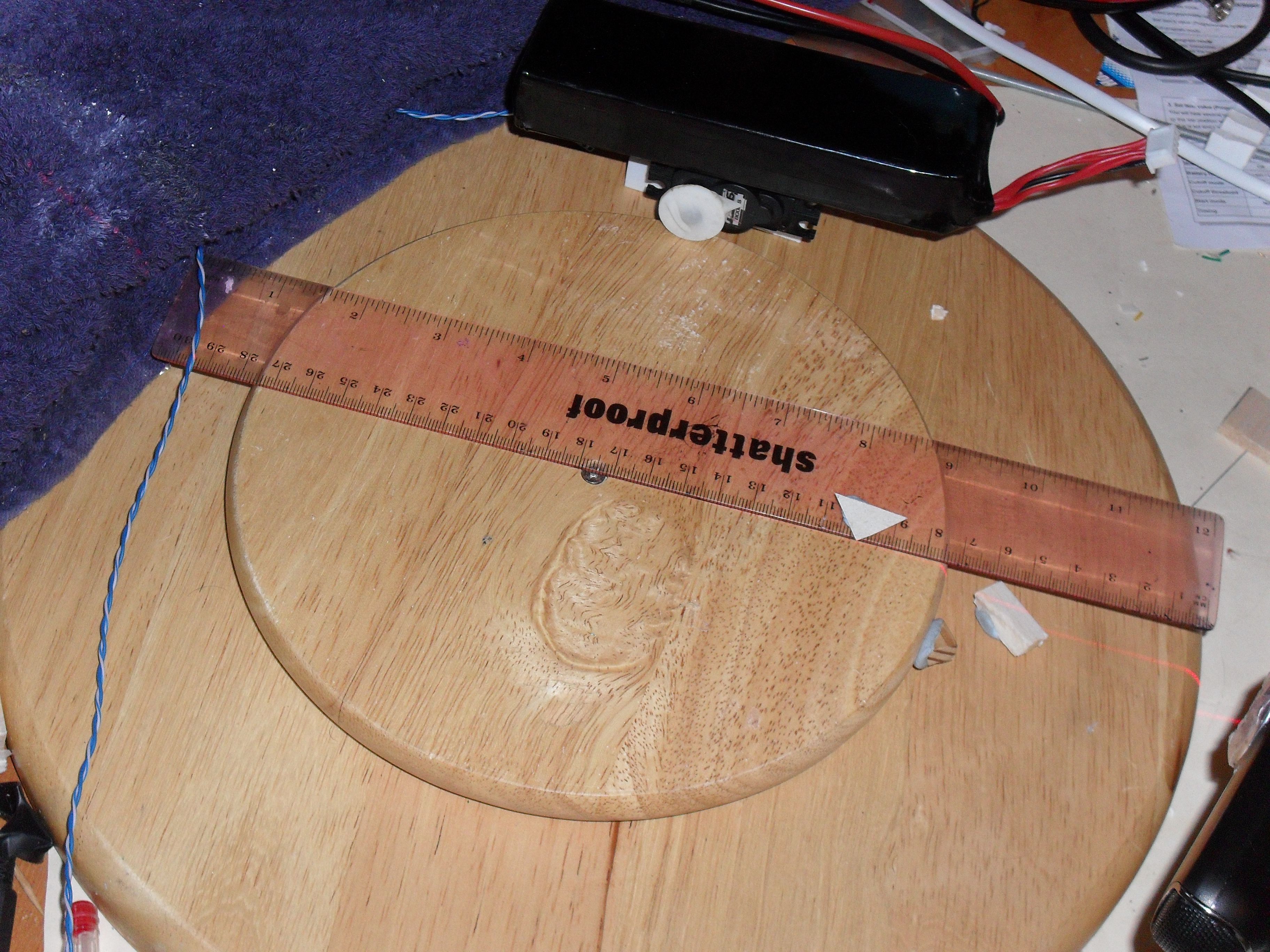
4. Remove the set square and put a ruler on the turn-table, lined up with the laser. Mark on the ruler a known distance that the camera can see. The distance from the center of rotation on the table to that point is parameter rawhorizzd (again, units are arbitrary), and the location in the image is parameter rawflat.
For example, a triangle of card is blue-tacked to a ruler at 100 mm point, and the ruler crosses the center of rotation at the 175 mm point, giving a distance between center of rotation and the triangle of card as 75 mm. I didn't start from the end because the ruler would fall off. Parameter rawhorizzd is set to 75 (ie. mm), and parameter rawflat is set to where the laser meets the marker, here.
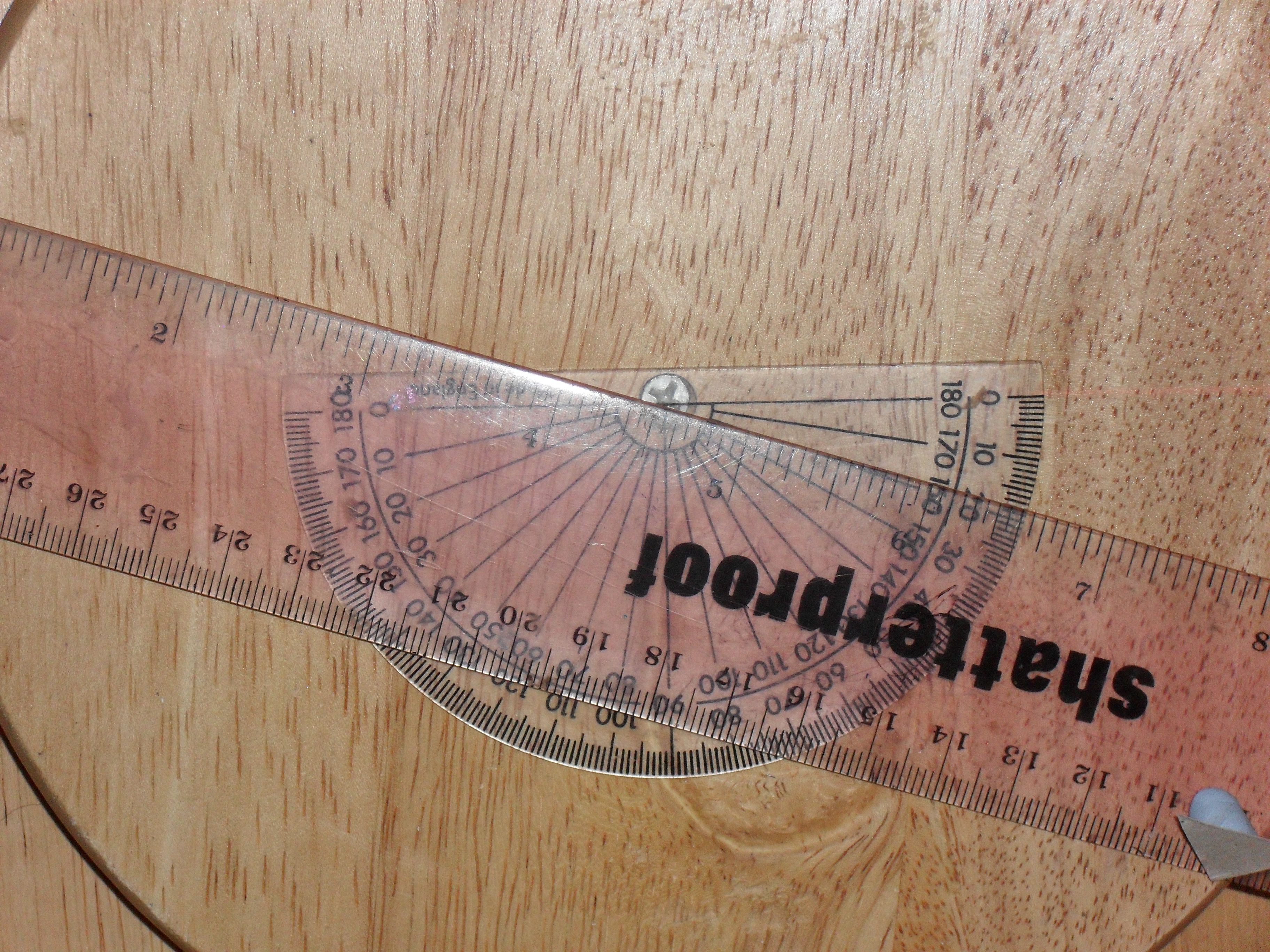
5. When viewed from above, from the center of rotation, measure the angle between camera and laser. Best done with a protractor and ruler. Line up the protractor to be at 0 for the laser, then put a ruler on the protractor and rotate in around until it appears vertical in the camera image - or simply points to the camera. This angle is parameter "angle".
6. Measure the camera horizontal field of view. For the 9000 Pro it is around 70 degrees, probably varies with focal distance, but doesn't seem to change the resulting scan much. 70 to 80 looked pretty much the same to me.
7. When viewed from above, measure the physical distance between the camera and the center of rotation. This is parameter "w", using the same units as the other physical parameters above.
And that is it. A long list, and care needs to be taken, but they only need setting once.
Once all the above is set-up, you are ready to start scanning.
1. Place the object on the turn-table, switch on the laser, start the turn-table rotating, looking something like this on the camera and this viewed from above. You can also see the battery weighing down the servo. The raw view looks like this.
2. Select mode DM (Depth scanning mode) and Depth view.
3. Make the room dark, and when the mark on the turn-table meets the fixed mark, click Start (example).
4. During scanning, Depth view will show pixels that are being used to calculated depth. The top is probably noisy, picking up scattered low light from the background. The bottom is the laser hitting the turn-table. The middle area is where it hits the object. You can also select StripDepth view, which shows all frames and their captured depths as an image. You should be able to see parts of your object, though generally there is not enough contrast to really pick it out.
5. Leave it scanning until the mark on the turn-table meets the fixed mark, click Stop.
6. Turn off the laser, turn on the lights in the room and let them warm up.
7. Select CM (Colour scanning mode) and Colour view.
8. When the mark on the turn-table meets the fixed mark, click Start.
9. During the scan, you will see colour dots, using the same positions as when the depth was scanned. You can also select StripColour view, which shows the scanned colours as an image. This image will be used as a texture when saving the scan (cat example).
10. When the mark on the turn-table meets the fixed mark, click Stop. UVCto3D will scale the resulting colour scan if it uses fewer frames than the depth scan. It will not scan more frames than used in the depth scan, as it does not know the location of the pixels to capture. Scaling with fewer frames will create distortion.
11. Click Save (in the view selection menu, for no particular reason), and the scan will be saved. The depth information will go into a .obj file, which will point to a .mtl file, which points to a .png containing the colour scan. Note it is possible to only do a depth scan, UVCto3D will complain when saving but the resulting file is (mostly) valid. When saving, UVCto3D will regenerate the pixel to 3D coordinates based on the parameters in the calibration settings. So it is possible to scan once, see the result in MeshLab, tweak the settings in the configuration and save again. Knowing which settings are wrong is not obvious.
Notice I didn't mention manually resetting the position of the turn-table or changing its speed, I assumed you would patiently wait for the turn-table to come around again. The above instructions are one way of doing it, your turn-table and lighting set-up might need a different procedure.
Load the resulting scan into MeshLab and trim the noise.
Load the texture into the GIMP, try using Colours->Auto->White balance or ->Normalise. Note it is possible for the texture image and 3D data to not exactly align. It is all down to turntable rotation and how busy the computer is. You can use the GIMP to remove columns from one end, and either add to the other side or delete them entirely. The .obj refers to coordinates in the texture by numbers 0 to 1 for x and 0 to 1 for y, so changing the image dimensions does not invalidate the .obj.
Having just tried this, it is easier from the command line:
pnmcat -lr <(pngtopnm < cat.png2 | pamflip -lr | pnmcut -l 30 -t 0) <(pngtopnm < cat.png2 | pamflip -lr | pnmcut -l 0 -t 0 -w 30) | pamflip -lr | pnmtopng > cat.png
Where the texture was copied to cat.png2, and a column 30 pixels wide was swapped from right to left. pnmcut is easiest to use from the left, so I cheat and use pamflip to make the left the right, then pamflip the result back again. The 30 pixels was found with a little trial and error.
Reproduce the object with the 3D printer you also have - or pay to have it printed.
UVCto3D V1.1 source
cat .obj+.png raw, denoised
Laplace smooth
Written by Richard Gregory (r.gregory at liverpool.ac.uk), mostly using code from previous projects.
Original idea was taken from the Steve Baker's Linux 3D scanner project, that also uses a turn-table and fixed laser. It takes as input a series of jpegs, assumed to be filmed from a standard camera in movie mode and then the avi converted into individual jpeg images. It produces a depth only .ac3d format file. Consequently, it is offline capture only, has no colour scan phase, and it is incredibly slow. Only now UVCto3D has been written do I see the 3D scanner forked into grape3D, something more complete.
The UVC code came from uvccapture by Gabriel A. Devenyi, which has been the mainstay of all my camera orientated projects.
Peter, who supplied the Lazy Susan and helpful comments.