Abatis
Home
These pictures show the end result of liquid cooling a Celeron 1G, with Geforce4 MX440 in a full tower case. Also cooled is the PSU and HD, though with hindsight the PSU cooling was probably unnecessary. The project used a ready made pond pump and many hours cutting, soldering and figuring out, copper was used throughout, copper plate for the water blocks and copper sheet for the radiators. The best reference for this sort of stuff is http://www.overclockers.com, in the water cooling section. This project was helped along by the information contained in those articles.
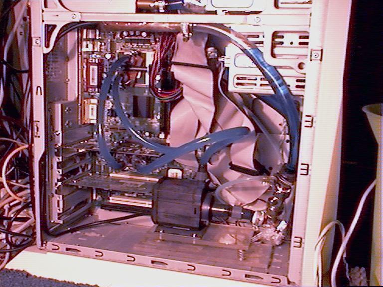 These two pictures show most of the system, the pump, the graphics card and CPU water blocks, the filler tube and isolation valve. The outlet on the top of the pump drives glycol to the graphics card, from the graphics card to the cpu and then running behind IDE and floppy drive cables the glycol enters the PSU. The visible pipe in the PSU is the exit pipe running to the HD. The hard drive itself is wrapped in a Brown Bread (a Dynamat clone) to reduce noise, just visible is the foil wrapped surface of the brown bread. Entering the pump from the right is the pump feed, from a tee which acts as air bleed when the isolation valve is open. When closed the system accounts for expansion via the small silicon tube that connects the system to the expansion tube. So, when closed the computer operates anyway up, the air in the expansion pipe moves but never enters the main flow. The returning fluid from the radiator can be seen better below, entering the tee from the right. Also connected to this return pipe is the small bore silicon expansion tube, this is out of sight behind the cables. Just below the PSU and HD level, there is a blocked off copper pipe sealing the expansion tube. All the pipe work was either 8mm or 15mm copper, with 8mm ID polythene tubing from the pump outlet to the PSU and 15 OD polythene tubing everywhere else. The expansion tubing made of silicon is standard modelling methanol fuel type. The pump is a 5 W (drawing 10 W) Enheim, bought from http://www.petsparade.com using the supplied fittings. The pump itself is mounted on a 5mm perspex plate, which is mounted onto another perspex plate with 3 small springs and some contact glue. This keeps the pump silent, vibration can be felt on the pump but not heard as vibration is entirely absorbed by the springs.
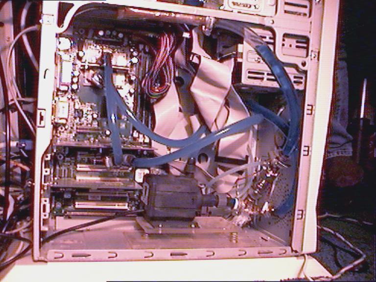
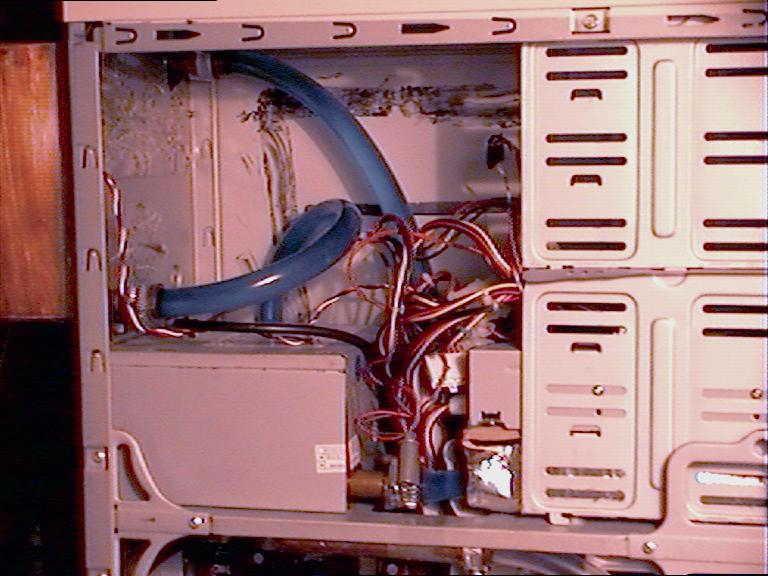 At the top of the full tower case, the PSU is mounted in the standard position with the 3.5" HD placed in a 5.25" bay, wrapped in sound absorbent material and jammed in by a CD rom directly above. From the bottom of the case, the glycol then leaves the PSU and enters the HD cooler, this takes the fluid along one side of the HD in copper pipe, soldered to a copper plate screwed to the HD. A 90o bend and some polythene tube then takes the glycol to the other side of the HD and another copper pipe with copper plate. The flow from the HD can then be seen here coiling up from behind the PSU and entering the bottom of the radiator. From the radiator glycol flows back down to the bottom of the case to the pump.
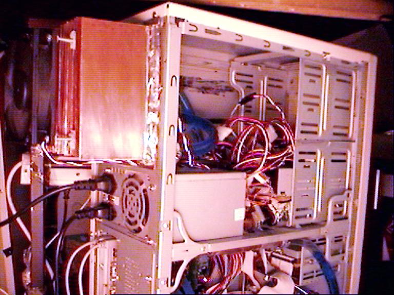
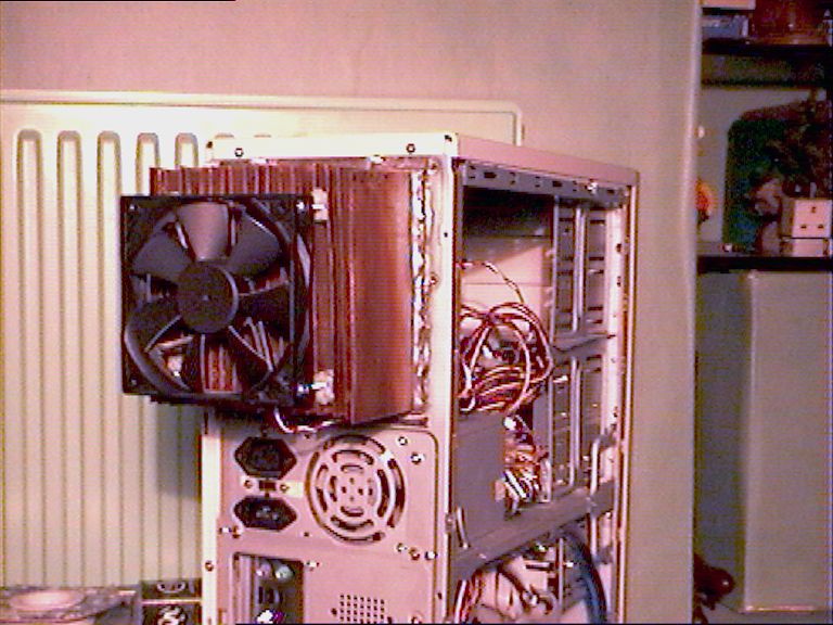
Looking from behind, the radiator is a copper box, 15cm x 15cm and 5mm deep containing the glycol. Onto this 19 15x8cm copper plates were soldered on, resulting in a surface area of 4560 cm squared, approximately equivalent to two case sides - but that is another story. A 12 cm fan is then mounted onto the fins, although designed as 12 V it is wired to run on 5 V as this creates enough cooling while being silent.
The end result, a wrapped HD, a slow moving 12cm fan and a slowed down PSU fan creates a very quiet system, guesstimated to be around 20dB, ie. only audible in otherwise total silence. Temperatures show the CPU block could be better, at around 12° C above fluid tempurature. The fluid tempurature is around 8° C above ambient. HD tempurature follows fluid tempurature at 2° C above. The 12cm fan runs at around 1100 RPM at 5V, instead of 2200 RPM at 12V, the speed of the PSU fan is unknown.
Update: After what is now many months of use the choice of glycol has shown its benefits. There have been no other additives and the only change in coolant has been a whitish deposit on the pipes, which then comes off if the pipe is squeezed. As this only appears where there is flow and not on the filler/expansion pipe I assume this stuff is particles of plastic from the pump impeller housing - after this length of time there must have been some wear.
There have also been two leaks, both on the gfx card block, both bad soldering. The first time around the block was re-soldered, the leak was on a joint. The second time the leak was in the middle of what should have been solid plate. I'm told a flaw in the soldering can leave a tunnel of flux/dirt that will cause a very slow leak some distance away from the joint. Rather than drain the system it seemed like an good idea to use super glue, it seems that was all it required.
One point from the first leak. Glycol is not very conductive but it is corrosive. The first leak killed a network card, glycol had puddled on the card for a few days before the network card started to fail (with checksum errors on ping packets). Solder joints were stained black, but after cleaning the card didn't show any signs of life, not surprising considering that when the power was switched on a tiny speck between tracks lit up and smoked.
Last modified: 11/06/03
Home